A friend of mine approached me a couple of months ago, asking if I could find a use for a set of five VHF radios (Motorola Radius M110s) he had recently become the owner of. He’s had a fondness for APRS for a while, and has often suggested having a set of ready-to-deploy APRS tracking beacons available to drop into vehicles when providing support for events, both with RAYNET and outside of it. The obvious thought occurred, and I set about looking into the feasibility.
Another mutual friend of ours, Tom M0LTE, had already designed some rather excellent Arduino-based tracking beacon boards, and after a quick chat with him, we established that he had five such boards left. He kindly agreed that they could become the basis for the project, and in October the handover was done. I then started procuring the rest of the parts required in order to get these units built. The normal places people look for semi-bulk components are eBay and AliExpress (the former being slightly more expensive, and the latter being better for bulk purchases), but as I had some spare Amazon account credit, I started looking there for component options. To my surprise, they had almost every component on the BoM list (in fact, they did have all the components, but there were a couple I sourced elsewhere – more on that later), at competitive prices. Yes, they mainly came from third-party sellers on the slow boat from China, but that just meant that the components arrived in manageable chunks and allowed me to build the boards piecemeal rather than having an overwhelming pile of bits to deal with.
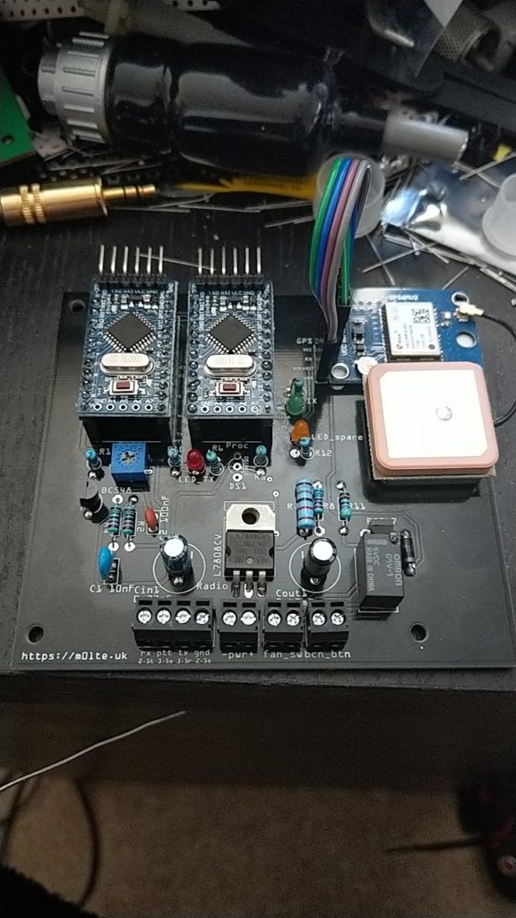
There were a couple of ‘gotchas’ with the component options – firstly remembering that not all Arduino Mini Pro units are equal. There are, in fact, 4 completely different variants of the Mini Pro – both 8MHz and 16MHz clock speeds, designed for both 3.3V and 5V power inputs. The particular Arduinos that this build requires are 5V 16MHz units, so ensuring that they’re the ones you order is key. The other ‘gotcha’ to look out for was a slight mistake in the PCB silkscreen labelling, and the BoM, for the relays. The board and BoM both suggest using G5Q relays, but the correct ones to use (identified the hard way, having ordered G5Qs which didn’t fit, and then checking the RS part number provided) are G5V relays – a smaller form factor and an extra pair of pins, allowing it to switch both + and – for driving a fan. Unsurprising, as the initial builds weren’t completely populated during testing, and not a problem. If anyone needs a set of 5 G5Q relays, let me know – they’ve been consigned to the “bits box” until a use is found for them.
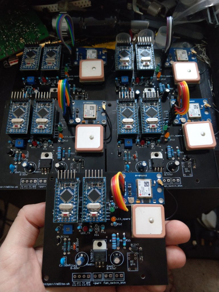
I opted to mount the Arduinos in header sockets, so they would be removable. I also opted to mount the GPS units the right way up on the boards, with double-sided foam tape to stick the PCBs and antennas to the main boards, so needed to buy some 0.1″ jumper cables and extra pins to connect the GPS modules to the PCBs with. Fortunately the pins arrived in the same package as the Arduino header sockets, allowing me to kill two birds with one order-stone. The Ublox GPS modules are pretty smart, and the specific ones I got can run over a relatively wide voltage range, though the circuitry in this case was all 5V. First fix took about ten minutes as they’d never been powered up before, but after they got a fix and stored the almanac, cold start time reduced to less than two minutes to first fix. Connecting the GPS modules to a USB UART (I have a multi-voltage one for various jobs) allowed me to interrogate them using the Ublox software, and see what was going on. The main thing being that they worked flawlessly and so far seem to be pretty reliable even though they were, to put it politely, dirt cheap!
The project has been a bit of an education for me – I found myself having to reacquaint my brain with resistor colour codes and capacitor number labels, along with reminding myself of the equivalent micro Farad and nano Farad ratings on some of the components I received, to make sure they were compatible. I also found myself needing to learn a bit of basic Arduino programming – not only how to find and install the right dependencies to flash the firmware images to the Arduinos, but also how to add some extra functionality. The image Tom had written, whilst pretty comprehensive, did not yet contain any support for the LEDs (I opted for 3 colours of LED from my parts box), nor did it contain any code for the temperature sensor, relay trigger, or beacon button. So far I have added the LED support and an LED power-on self-test routine (which showed me a bad solder joint, so has already served its purpose once!), and the remaining functionality (temperature sensor thresholds to trigger the relay and start/stop the fan power feed, and beacon button triggering for transmitting a position packet) is work in progress. Creating the Github ‘pull request’ to merge my changes into Tom’s image code was, again, an education in itself, but for someone who doesn’t do programming or write code normally, it was all a very useful learning opportunity!
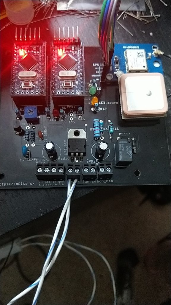
The PTT LED code is currently a bit of a dirty hack – the current hardware design is such that the PTT LED is controlled by the processor Arduino, and as such has no direct feedback from the TNC or the actual PTT pin. I’m looking at a small modification, to parallel the PTT link from the TNC to transistor with a second link back to the processor Arduino, which will then be able to sense the PTT being enabled, and drive the LED correctly. Currently the LED indicates when the processor board sends an instruction to the TNC to transmit a packet, and has a small delay hard-coded in to make the LED stay on long enough to be visible, and more representative of the actual transmit period. Once I add the jumper wire, I’ll tweak the code so that the PTT LED indicates both the packet send instruction, and then the subsequent PTT from the TNC.
The project is not yet fully complete – I’m waiting for the right power connectors for the radios to arrive (if anyone’s ever stuck looking, the power connectors for Motorola Radius M110 rigs are ITT Cannon SureSeal two-way connectors (thanks to Dom M0BLF for identifying) – you need to buy the “socket” housings as the radio has the “plug” sized housing on the back), waiting for the temperature sensors to arrive from China (the seller sent me some MOSFETs instead of temperature sensors by mistake, as they are the same form-factor and component package, but a quick couple of photos and e-mails prompted them to then ship a replacement set of items for me), waiting for some twin-core power cable and Anderson PowerPole connectors for the outside (at the intended recipient’s request), and then building the interlink cables for the radios (I’m reliably informed that the DB9 connectors on the rear will work for PTT and audio I/O). I’ll be leaving it for the intended recipient to source boxes and fans, and work out the finer points of mounting them sensibly with adequate ventilation etc, but by then the extra code for temperature sensing, relay triggering and the use of the “spare” LED for indicating that the fans should be spinning will be written and tested. The code for the beacon button will also be added, and I’m in discussion with Tom about a revision 2 hardware design. This will hopefully include the jumper wire I mentioned above as a PCB track, and possibly involve the use of SMD components for the sake of cost and size. We estimate that the resulting board could probably be shrunk to at least 75% of its size, if not less, by doing so.
Recent Comments